Boat Anchor
refurbs
This is a description of a few vintage HF radios and some of the actions required to bring them back to life. While information for servicing these radios, including schematics, manuals, and service bulletins, is available to varying degrees over the internet, the experience base is dwindling, and online support is scarce compared, for example, to what's available in the maker community. Documentation also appears to be vanishing as copyrights are acquired and enforced by third parties. Anecdotal accounts like this will become increasingly important to radio enthusiasts as time progresses and the situation worsens.
None of the radios described here is particularly remarkable. All exhibit design compromises and are the products of less sophisticated design and manufacturing eras. It is hard to believe that all of them were prototyped or tested seriously before being mass produced. Nonetheless, they are interesting for their quirks and foibles. All are perfectly capable of carrying out communications on the HF bands, a technical problem that was mainly solved a half century ago. All of the transmitters have given rise to good reception report at one time or another. Perhaps most interestingly, the radios have some problems in common despite coming from different manufacturers and different times.
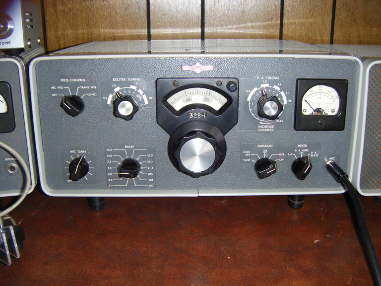
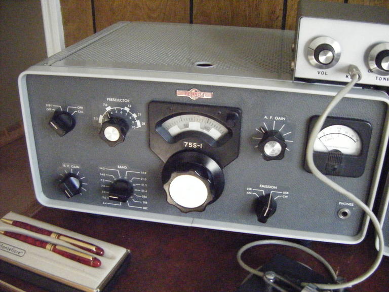
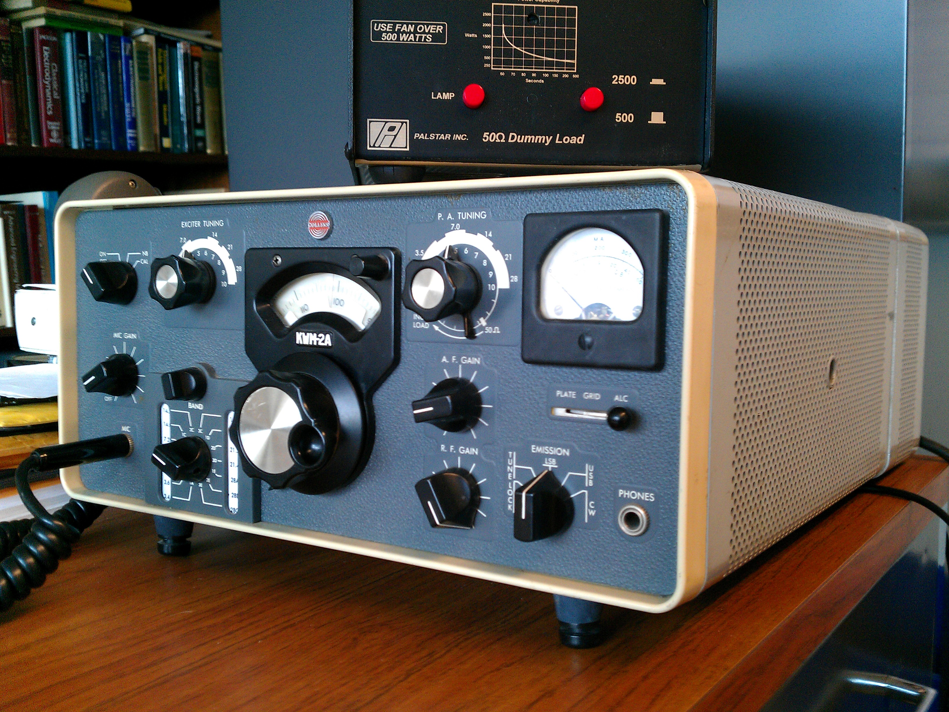
Collins 75S-1, 32S-1, 516F-2.
These classic radios were acquired after what appeared to be many years of disuse. The power cords were frayed, and some case hardware was missing. Their cosmetic conditions were pretty good, however, with the exception of dents caused by stacking and some unfortunate holes drilled in the power supply case. The aluminum chassis, shields, etc., in these radios clean up nicely, making repair rewarding.
The 516F-2 power supply has two 8 H chokes. The one on the high-voltage supply hummed noisily when the transmitter was idle but not when current was drawn. Swapping it with the choke in the low-voltage supply circuit, which always carries current, remedied the noise problem. This was fortunate, as replacement chokes are obtainable (see Nationwide Radio & Eq. Sales LLC for example) but expensive. This particular power supply had been modified and fit with a 4 ohm speaker, one that was now in very poor condition. A duplicate speaker is offered at low cost by Electronic Plus.
The 75S-1 receiver had no serious problems aside from a broken coupling in the emission switch, a misaligned shaft in the band switch, a gassy 6DC6, and a frozen PTO vernier drive, which came loose with minor mechanical adjustment. Even after alignment, sensitivity on 15 m was poor. Simply rearranging the components in the RF tuned section beneath one of the shields under the chassis remedied this problem. Removing the shields in the first place was more difficult, as the nuts securing them were frozen solid. Applying some metal polish to the threads of the screws ultimately made it possible to remove the nuts without damaging the shields. The shields, which are made of low-permeability material, are hard to replace and not to be trifled with. Securing them snugly to the chassis is essential for preventing instability and oscillation.
The PTO on this particular receiver produced low output (see this guide), and the output from the cathode follower was subsequently low for driving a transmitter. This problem was remedied in large part by tuning T301 for maximum midband output, an option that is not mentioned in the manual for some reason.
Some crystals were missing from the receiver, but replacements were acquired for a modest cost from QuartsLab of Dublin, one of the last made-to-order HC/6U crystal suppliers still in existence, it seems.
Being unlikely to possess the F455Q-5 500 Hz CW filter for this radio any time soon, I found it useful to incorporate a Q-multiplier for CW operation. A Heath HD-11 works well here. Likewise, a tunable BFO seems like a real necessity for this radio, and so a homebrew unit based on Ten-Tec's 455 kHz tunable BFO kit with an extra gain stage added was pressed into service. The AC-coupled output from this very stable unit can be fed directly into the BFO test port of the radio. Another spare port was used to provide a means of switching off the internal BFO when the external one is used. Combining the tunable BFO with the Q-multiplier, the functionality of this receiver now approaches that of a 75S-3 in many respects.
The 32S-1 was more problematic. Like the receiver, the transmitter had a broken emission switch coupling and a misaligned band switch shaft. Some crystals were also missing. The PTO vernier was frozen but responded to some mechanical adjustment and, like the receiver PTO, turned more freely with time and use. More critically, the band switch cable was down to its last thread. Fortunately, suitable replacement cable (painted, nylon-covered woven stainless steel) can be purchased inexpensively from any big-box craft store (as bead wire). Attaching a small spring to the free end of the cable makes it much easier to maintain required tension when securing it to the take-up reel.
Every paper capacitor in the unit had to be replaced, all having failed in their DC-blocking function. This especially affected circuits where the capacitors establish time constants, e.g., in the AGC and VOX delay circuits. C119 in particular posed problems, since its free end was tied to the 275 V rail (which actually carries more than 300 V under contemporary line voltage) rather than to ground, where it is better connected.
The original VOX circuit was poorly designed and, among other problems, caused R89/R112 to run very hot. These were replaced with a 100 k, 8 W resistor combination. Rebalancing the voltage divider, R88 was replaced with a 890 ohm resistor in series with a 5 V zener diode. This provided the necessary stiffness for the divider while allowing reduced power dissipation and more consistent operation. A similar modification was described here it turns out, and applies equally well to the kwm-2a. It proved worthwhile to implement SB-3, adding a variable time constant control. Similar modifications were incorporated in the 75S-3, which could equally well be copied here. (See the Collins Collectors Association for a complete list of service bulletins and manuals.) SB-4A also proved worthwhile.
As is pointed out in these service notes , there is an inherent problem with the way C6B is wired, such that its voltage rating is exceeded when the emission switch is in the LSB and USB positions. Upon being switched into CW mode, a symptom of the problem emerges, which is a chirpy tone oscillator. Instructions for correcting the problem are given on the site. Even with the correction made and the paper capacitors in the tone oscillator replaced, the unit continued to chirp annoyingly during CW transmission. This problem was remedied with the replacement of V11.
Finally, the 32S-1 exhibited instability and the tendency to oscillate even with no drive applied. Along the advice of the relevant service bulletins, C56 was replaced with a comparable feedthrough capacitor from Surplus Sales of Nebraska and all the shield covers beneath the chassis were also re-seated. These actions, combined with careful alignment, remedied the instability problem.
While diagnosing different problems with the transmitter, I was frustrated by a lack of information about the nominal signal levels for the different stages. The table below lists rough measurements of the signal levels present during CW transmission. Peak RF voltages are given.
| FL1 input | 10 V |
|---|---|
| V4 pin 2 | 600 mV/ 3 V VFO off/on |
| V5 pin 2 | 300 mV |
| V6 pin 1 | 20 mV |
| V7 pin 2 | 100 mV to several V |
A local vendor sells RG-62/U, which was used to connect the transmitter and receiver crystal oscillator and VFO ports. This coax was commonly used in old 10-base-2 ethernet wiring and is still rather common. While it provides the best impedance match, its use in short runs like this is not critical, and RG-58 serves just as well.
The main flaw with the 32S-1 is the way it generates CW - by feeding the output of the tone oscillator into the balanced modulator in the same way it generates SSB from any audio signal. This method is prone to generating spurious emissions arising from the carrier and harmonics of the tone oscillator, which are not completely suppressed by the skirts of the mechanical IF filter. The same thing occurs with SSB but is unimportant where broadband audio signals are concerned.
The transmitter in question here had a full-wave bridge in the balanced modulator, providing improved carrier rejection over the half-wave bridge version used in earlier models. So long as the balanced modulator is properly balanced, spurious emissions in CW mode should not be a serious problem (at least in the event of barefoot operation.) The balance adjustment must be revisited from time to time, however. Some have noticed that the 1350 Hz CW tone is unnaturally high and suggested moving it down to a more comfortable listening frequency. This would be a mistake; the CW tone is matched to the BFO frequency offset and the IF filter bandwidth, and lowering it would allow harmonic frequencies to pass through the filter and increase spurious emissions gravely.
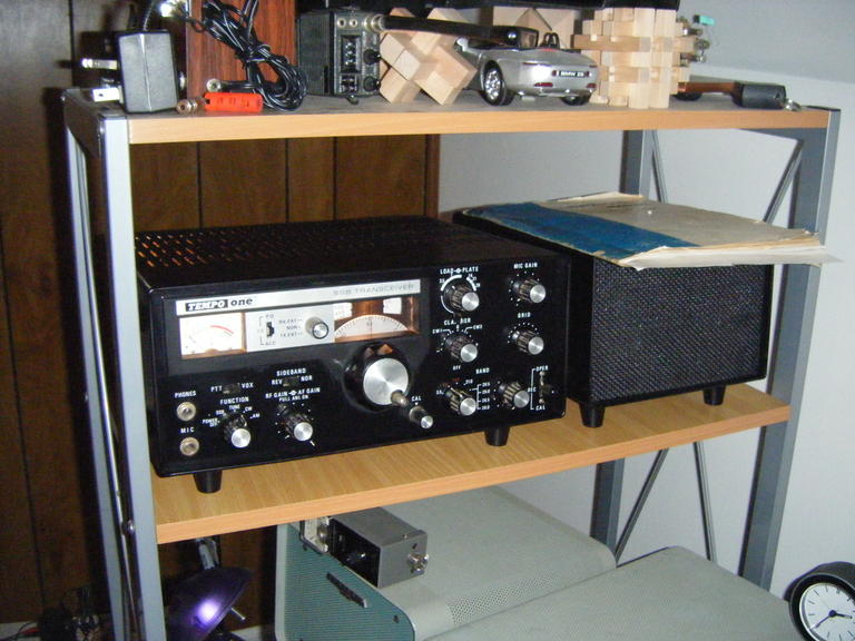
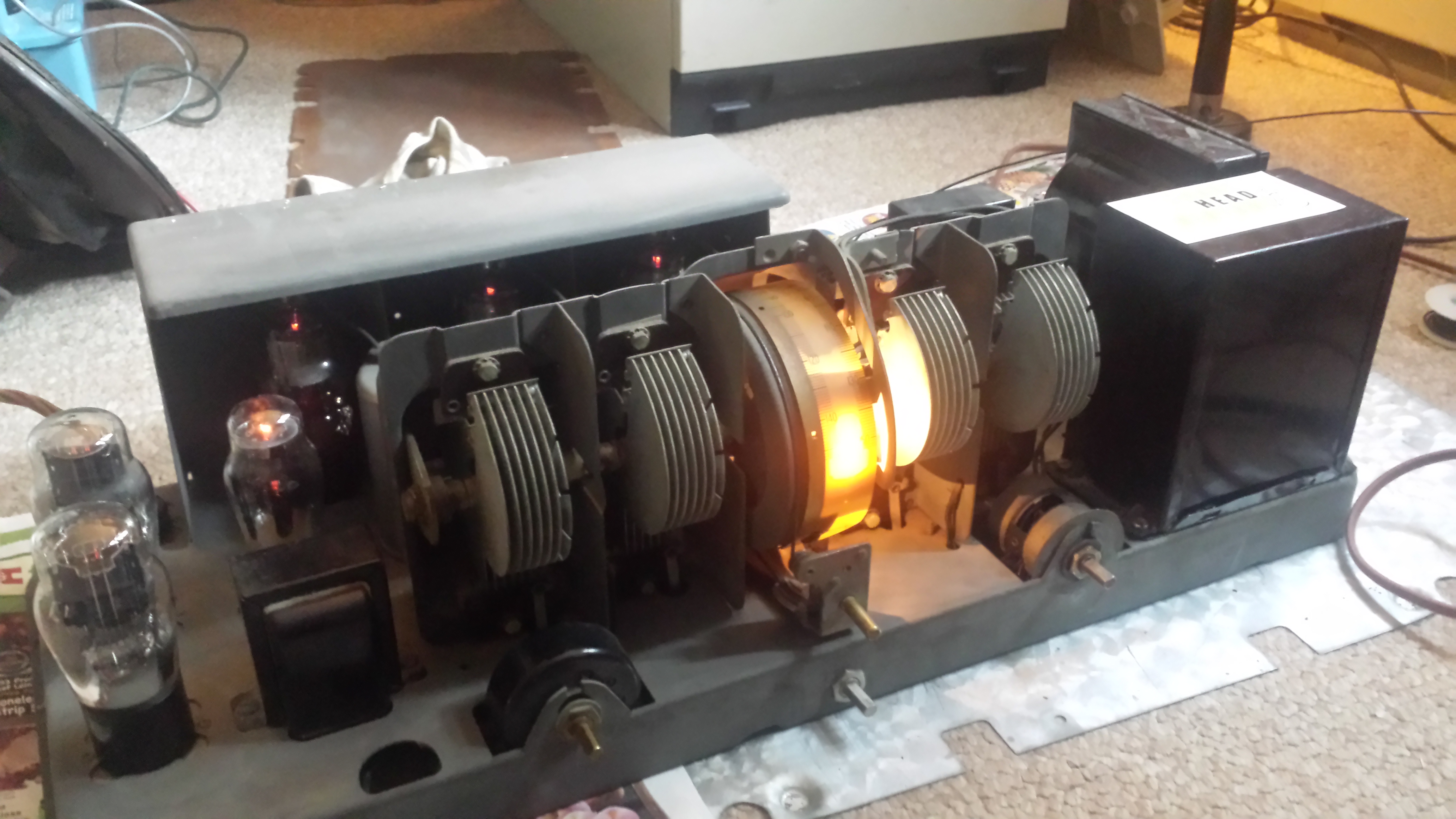
Henry Tempo One (Yaesu FT-200, Sommerkamp FT250)
This transceiver was acquired at a hamfest for a very small sum. The case was rusty, but the front panel was clean, the switches and dials worked freely, and all the tubes were present. The power supply also appeared to be in reasonable condition.
Like many other rigs of the same model, this one had been converted for CB use. Restoring it to its original condition involved removing a few yards of wire and returning the original 10 m crystals to their original position on the heterodyne oscillator board.
The transceiver did little when powered. A wire in L101 was found to be broken. disabling the receiver. D502 and TR502 had both failed. These supply 9V to the solid-state oscillators, which were consequently inactive. VR504 was also sufficiently mistuned to prevent the tone oscillator from functioning. L9 and L14 both had broken ferrite cores, preventing reception on 15 m. (New cores can be purchased from Surplus Sales.) Several other cores refused to turn at first but were eventually coaxed with the application of some heat from a low-power soldering iron. Finally, the noise blanker switch had failed, but another pole on the same switch was available as a convenient replacement. With these problems corrected, and the AGC set properly, the receiver came to life.
At first, the final amplifier bias current could not be brought up to 60 mA regardless of the VR103 setting. I feared faulty finals, which would have been unfortunate given the staggering replacement cost of the 6JS6 sweep tubes. However, the resistors in the bias circuit were found to have drifted out of spec., and with that corrected, adequate bias current became available. As a precaution, C55 was replaced with a capacitor rated for 2 kV to avoid a notorious failure mode. After careful alignment according to the instructions in the service manual, the transmitter produced rated power on all bands, and all seemed well, at least momentarily.
Once in service, the transmitter output power would decrease gradually but consistently following power-on. In addition, the output from the crystal calibrator would also fade over time until vanishing altogether. Both systems recovered after the radio was allowed to cool, and forced air mitigated both problems to some degree.
The crystal calibrator was repaired with the replacement of C306 and TR301. The transmitter problem was traced to C67, which is part of the ALC. Both capacitors developed temperature dependence over time. Forced air cooling continues as a precautionary measure.
The Tempo One has a number of idiosyncrasies. The voltage across the key line is over 100 V and can easily damage unsuspecting electronic keyers, even those with reed relays. The sideband has to be reversed for 40 and 20 m operation because of a shortcut in the design of the BFO. The receive/operate switch is unintuitive and can easily lead to inadvertent transmitting. There is no way to control transmitter power in CW mode from the front panel, and the sidetone frequency control is an internal adjustment. Sensitivity is poor on 10 m, although this can be corrected to some degree by replacing the RF amplifier tube with pin-compatible alternatives (e.g. 6EH7, 6DC6, 6EW6). The IF filter is adequate for SSB but too narrow for AM and too broad for CW, and no filter options are available. This rig may be a prime candidate for conversion to 6146 finals, although accounts on the web point to mixed success here. My particular power supply is unusual in that it lacks the 600 V taps found on most others, making conversion to 6146's or PL504's unattractive. For some reason, my power supply board is fully populated with diodes and capacitors (doubled), even though this is not reflected in the schematics.
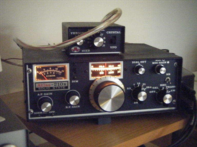
Atlas 210x
This is a solid-state rig from the late 1970's of U.S. manufacture. It seems to have been designed mainly for mobile SSB work and is unsuitable for CW unless paired with its base console. My unit came with both of its CA3086 ICs destroyed, perhaps by being powered in reverse polarity. These ICs are simple transistor networks that can be easily replaced with an equivalent or homebrewed. Beyond that, the radio functioned normally. It suffers from severe drift, at least for the first half hour of operation or so. (A workaround is described here .) The Atlas also suffers from transmitter instability, the thermal compensation in the final amplifier being inadequate. Care must be taken to make sure the final amplifier isn't overdriven and doesn't overheat during transmission. Furthermore, the directional coupler that senses excessive reflected power comes after the T/R switch and therefore offers no protection against a slow or failing relay.
Despite these problems, or perhaps because of them, the radio is well suited for digital communication modes. Because both sides of the communication link have automatic frequency controls built into their software, the drift problem is not critical. Because digital modes are typically engaged in at reduced power levels, there is little chance of runaway heating in the finals.
Lacking the base console, I constructed an external VOX unit for the radio that works both in CW and SSB modes. The VOX is based on a simple design from the '81 ARRL handbook and combines some switching features (shifting the carrier, unbalancing the balanced modulator, and disabling the MIC amplifier in CW mode) required by the radio and described in its instruction manual. The original VOX design was modified to have a single 12V supply, which is taken from the radio, and keys the radio with a small relay. The VOX circuit simplifies the use of digital modes as well.
Finally, the gain in the microphone amplifier in this radio is rather low. Absent an amplified microphone, the built-in amplifier (Q202B, PC 200D) can readily be modified for higher gain by changing its bypass.
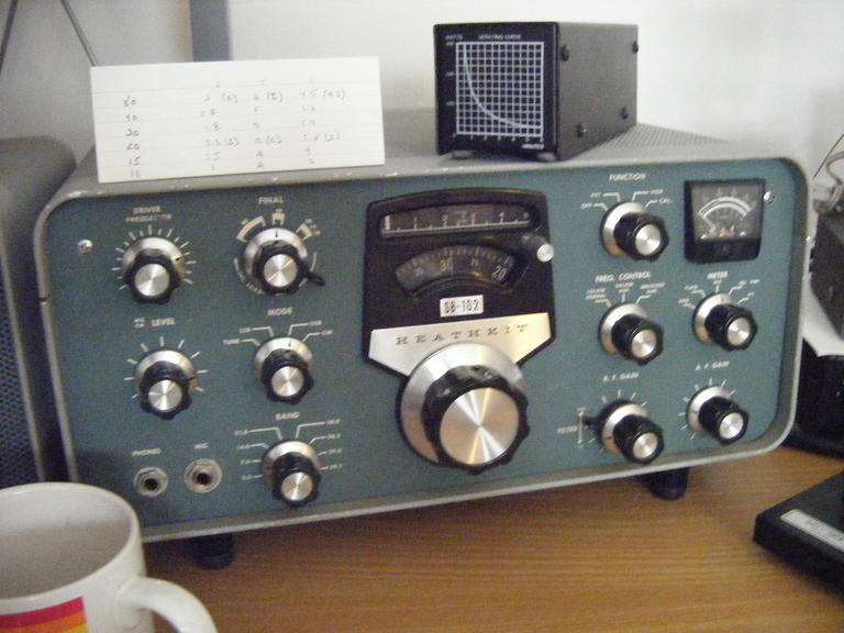
Heathkit SB-102
This radio was acquired in the early 1980s. It was a good investment; the radio worked then (after alignment and the replacement of a few crystals, tubes and belts) and continues to work now. (Replacement belts can be purchased from Agway, form their O-ring selection. Many other parts are carried by this supplier.) It is consistent and stable and exhibits little drift. It is easy to use and troubleshoot. The tuning vernier is much maligned but is actually smooth and reasonably accurate and doesn't slip or show backlash when clean and properly adjusted. The PC boards remain in good condition and show no heat damage. The radio is alone among the others in offering a 400 Hz CW filter standard.
The Heath SB and HW lines exhibit a number of common problems but also share a considerable knowledge base which can be used to understand and address them. Mine originally suffered from inadequate final grid current drive. The problem was resolved by 1) removing the fingers from the shield cover ( ref ), 2) retuning the IF transformer ( ref ), and 3) adjusting the passband tuning ( ref ). The driver plate resistor, R940, was also well out of tolerance, as was R7 which powers V16B in LSB and CW-transmit/tune mode. Information about the anticipated signal levels in the radio are given in this spreadsheet. Common problems with S-meter drift and the solution are described here. An extensive set of service bulletins is here. Finally, more practical hints and mods, including how to deal with AC hum in the audio, are given in this page.
The radio has an important deficiency that is possessed to one degree or another by the other radios. One can align and tune the heterodyne oscillator, driver grid and plate circuits, and IF circuits for peak RF output, or one can tune for peak receiver sensitivity, but because of inadequate buffering, one cannot do both. Service bulletin SBM-102-1 describes how to modify the preselector to help mitigate the problem. My unit has that modification, and while it is helpful, it is not a complete solution. The RF and IF sections in common (mainly T102) peak in different places during transmit and receive, and the user is forced to sacrifice receive sensitivity, transmit power, or both during alignment. Nevertheless, the radio can be tuned so as to meet transmit and receive specifications.
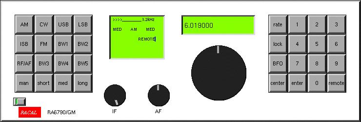
Racal 6790
This radio is well documented, and its modular construction and open layout are conducive to repair and adjustment. This is fortunate, as the design is replete with amplifier stages with biases and gains that require periodic adjustment to meet spec.
The radio's utility increases when its serial control capability can be utilized. Serial control also limits wear and tear on the front panel controls, which are somewhat delicate and prone to damage. Finally, serial control offers an easy means of adding memories and scanning capabilities.
Here is a software package which demonstrates serial control of the radio. It is intended for the unix operating system and makes use of the xforms library for the graphical user interface. Source code is included. Radio control is through an RS232 port. The hardware address for the radio is hardwired in the code and must be changed at compile time, if necessary. The interface is intuitive and functions much as the front panel radio controls do.
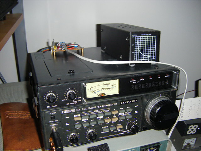
Icom 720a
While hardly a boatanchor, this radio is one of the first of the microprocessor-controlled solid-state radios to appear and is heavier (and sturdier) than most contemporary HF radios. It is also very well documented, but the layout is cramped, and repairs can be awkward. The radio features a number of relays (for T/R switching, the filter banks, and the input preamplifier), and cleaning these can solve many of the problems the radio exhibits.
The radio shown here suffered from a faulty transistor in the output driver stage. The bias current running through the remaining good transistor had been doubled somewhere in its history, and so the problem was not immediately apparent. Replacing the transistor and readjusting the bias current produced full rated output power.
The 720a has a digital interface that predates the Icom CI-V serial protocol. The interface is partially documented in a pair of QST articles, but even Icom of America seems to have lost the details. It uses a 4-bit parallel bus with two handshaking lines and a bus direction control line. It is not very fast (exchanges require approximately 100 ms to complete), and it is fragile; the Icom CPU crashes if the VFO is adjusted manually while digital I/O is in progress. Nevertheless, the interface adds important capabilities to what is otherwise a competent radio.
Here is a project which confers Icom CI-V serial interface capability to an IC-720a. It is built around a PIC16F84 microcontroller and uses a MAX232 to provide RS232 signal levels. It makes the radio appear to be an IC-735 and supports frequency, mode, and VFO reads and writes. It is not a comprehensive implementation of CI-V but could be made to be with some additional programming (and with an upgrade of the PIC). The project has been tested with fldigi, grig, and HRD.
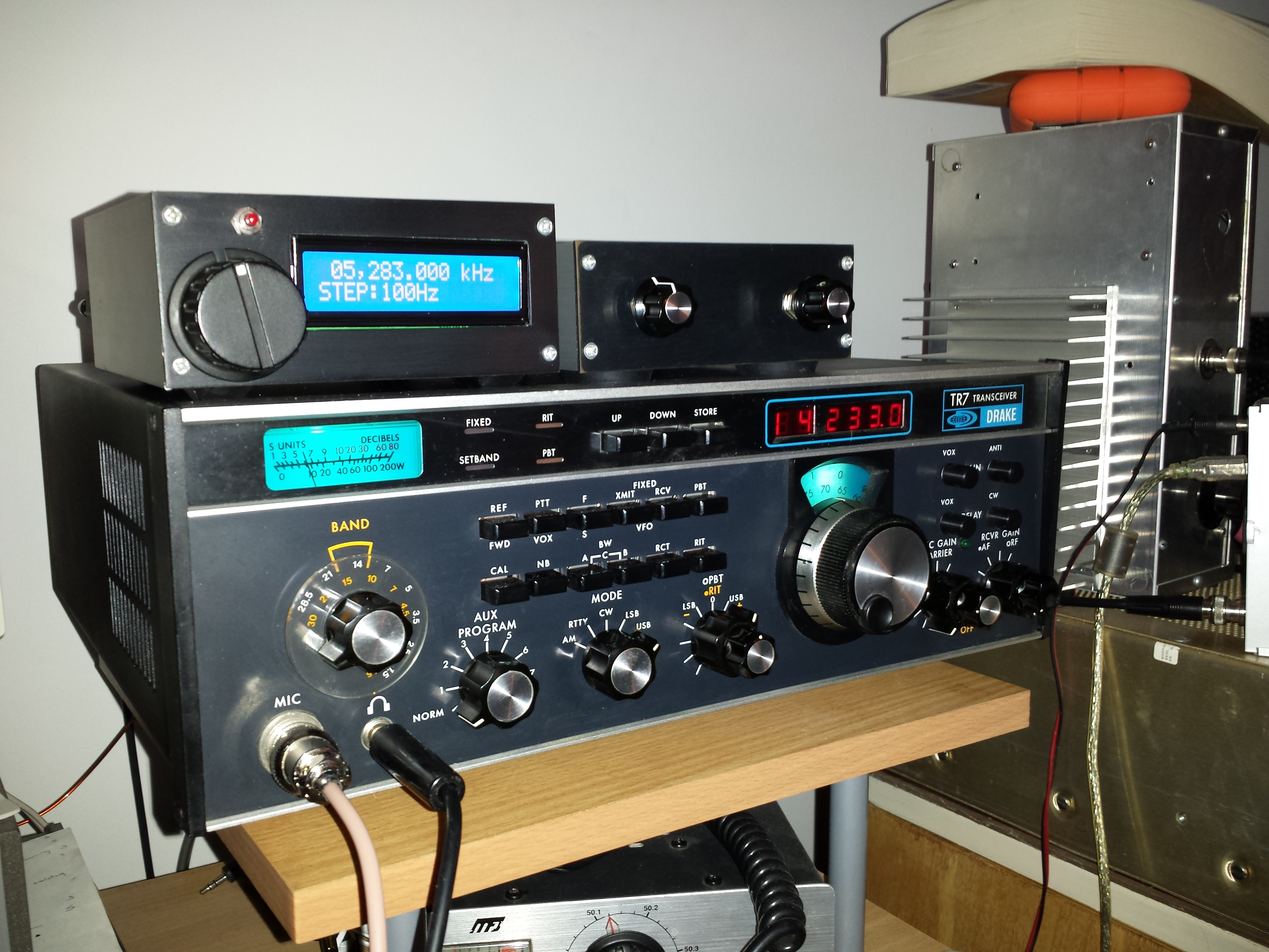
Drake TR-7
This radio came from a hamfest vendor who said that it received but didn't transmit. In fact, its problems were more extensive. A bad 14528 one-shot on the DR-7 board made it impossible to change bands. (Note here that a 4098 is a suitable replacement, although the timing capacitor may have to be changed.) Next, Q6 in the parent board was faulty, causing the PTO to be disconnected and the synthesizer to lose lock on transmit. Finally the driver transistors in the final amplifier needed replacement (with a matched pair of 2sc1969's.) After alignment, the radio worked according to spec. In all, this was a simple and an inexpensive refurb.
The TR7 is similar to but in most respects less sophisticated than the IC-720. It lacks a CPU and CAT control and is not fully synthesized, employing an open-loop, mechanically tuned VFO (PTO). The frequency display is actually a frequency counter, and setting the operating frequency can be awkward, particularly in split mode. The radio would benefit from an RF preamp and improved ALC and AGC timing. Internally, the radio is built of sparsely-populated circuit boards that utilize only low-level integration.
Even so, the TR7 is agreeable to own and operate. The transmitter is capable of producing more than 100 W and can tolerate a high duty cycle in digital modes. Rear-panel connectivity is excellent and makes it possible to improve the radio without modifying it internally. This one now has an external RF preamp, semi-active AF notch filter, and DDS-VFO with CAT control. Repairs appear to be relatively easy.
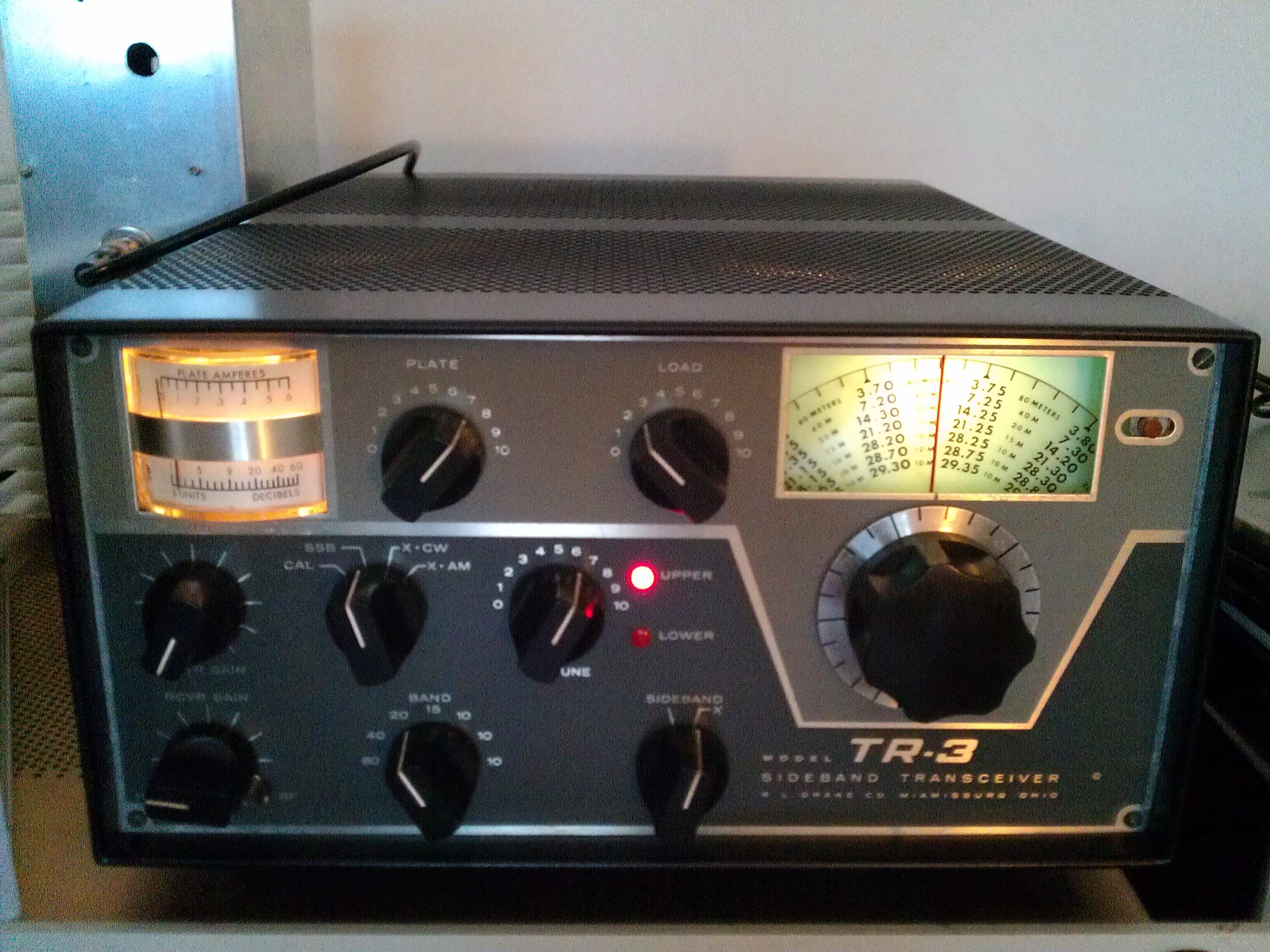
Drake TR-3
This radio, with matching RV-3 and AC-3, came from an SK by means of a club sale. The seller argued that the radio should be working since it was found connected at the SK's station. In fact, it was thoroughly inoperative. Most every stage of the radio was far out of alignment, and some curious mods inhibited operation further. Both the TR-3 and the RV-3 PTOs needed the ground strap modification described here. The rotary switches on the TR-3 and RV-3 needed cleaning.
After some attention, the radio functioned, but sensitivity was poor, and output power was low. The problem was traced to the 9-MHz "soup can" IF filter and the "X" section in particular which exhibited a very narrow passband and high insertion loss. This is evidently a common problem with the TR-3 and early TR-4 caused by aging of the filter crystals. Since replacement filters come at the expense of parts radios, bad filters in this radio are usually thought to be terminal.
A solution to the problem is offered by Inrad which sells an inexpensive 9-MHz 4-pole crystal filter kit with characteristics not too different from either of the original filters in the TR-3 soup can. The filter is unbalanced and has an impedance of 200 Ohms. It can be made to work in the TR-3 with the aid of 9:1 balun transformers at the input and output. For better performance, two of the Inrad filters could be used.
For USB/LSB operation, it is subsequently necessary to replace the 9.0 MHz BFO crystal with a switchable pair of crystals separated in frequency by about 3 kHz. Such a pair can be salvaged from the soup can filter. Switching can be accomplished by means of a reed relay, powered from the filament supply using a rectifier bridge. Note that it is vital that the legs of the bridge be bypassed by small capacitors (~0.022 uf) to suppress switching noise that would otherwise enter through the BFO circuitry. The relay can be controlled using the original rotary switch from the soup can filter which also controls the USB/LSB lights.
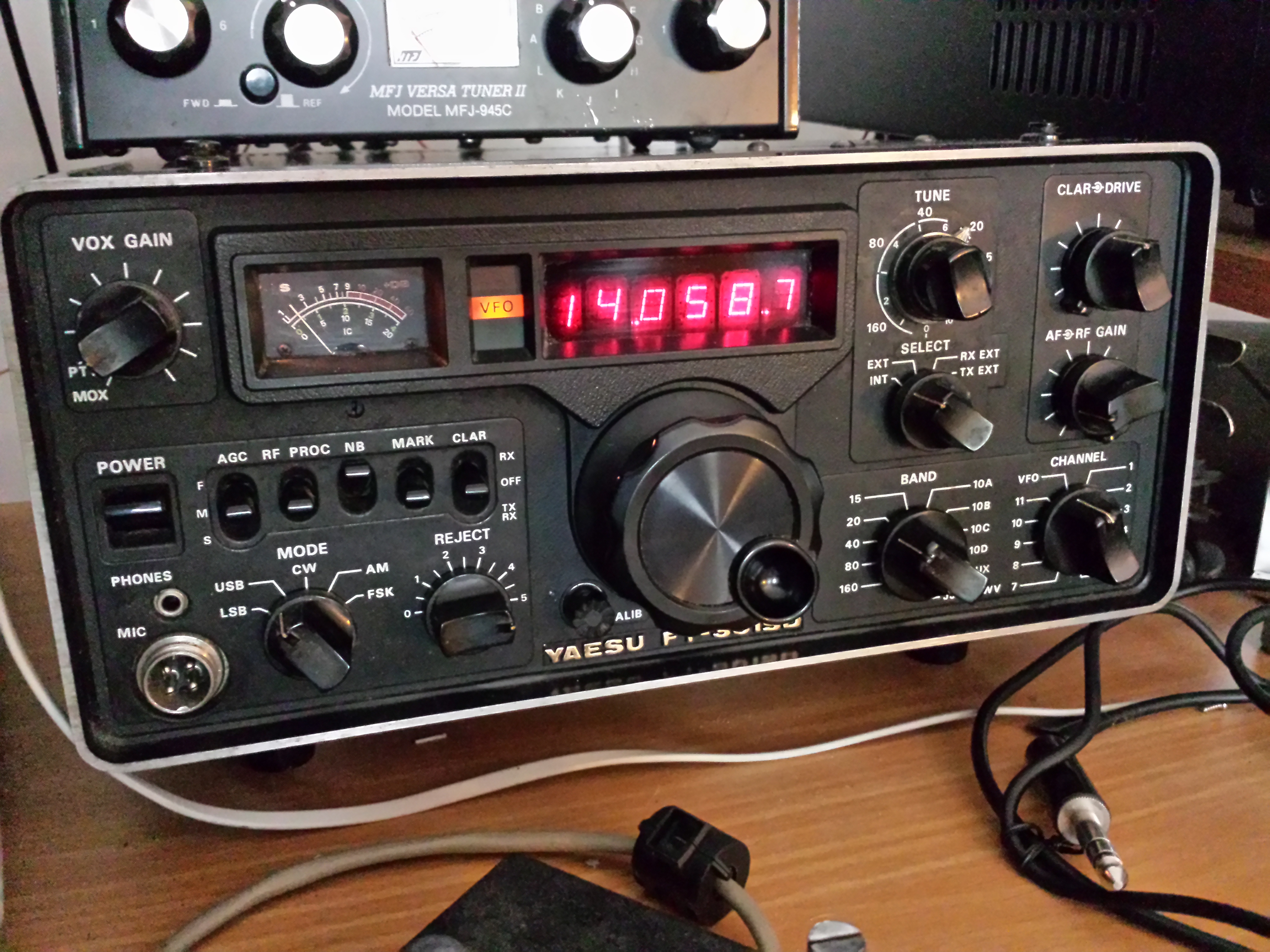
Yaesu FT-301SD
The FT-301SD is a well-built and well-documented if unspectacular transceiver. This version has a digital display but is missing the final amplifier (QRP version). One of the segments in the display was intermittent. The problem was corrected by introducing a diode in the power supply line to the display board to prevent display overheating. The only other problem with the radio was the failure of three of the LO crystals. Replacements were available from Quartslab.
The VFO in the FT-301 drifts badly despite any amount of fiddling with the temperature compensation trimmer. Fortunately, the external DDS-VFO built for the TR-7 is compatible with the Ft-301. CAT control became available with some additional programming. This upgrade turns the radio into a fairly good performer. It has more usable dynamic range than the other radios on this page which is further augmented by the IF notch filter. All it needs now is a final amplifier. The AN-762 from CCI would seem to be an appropriate choice.
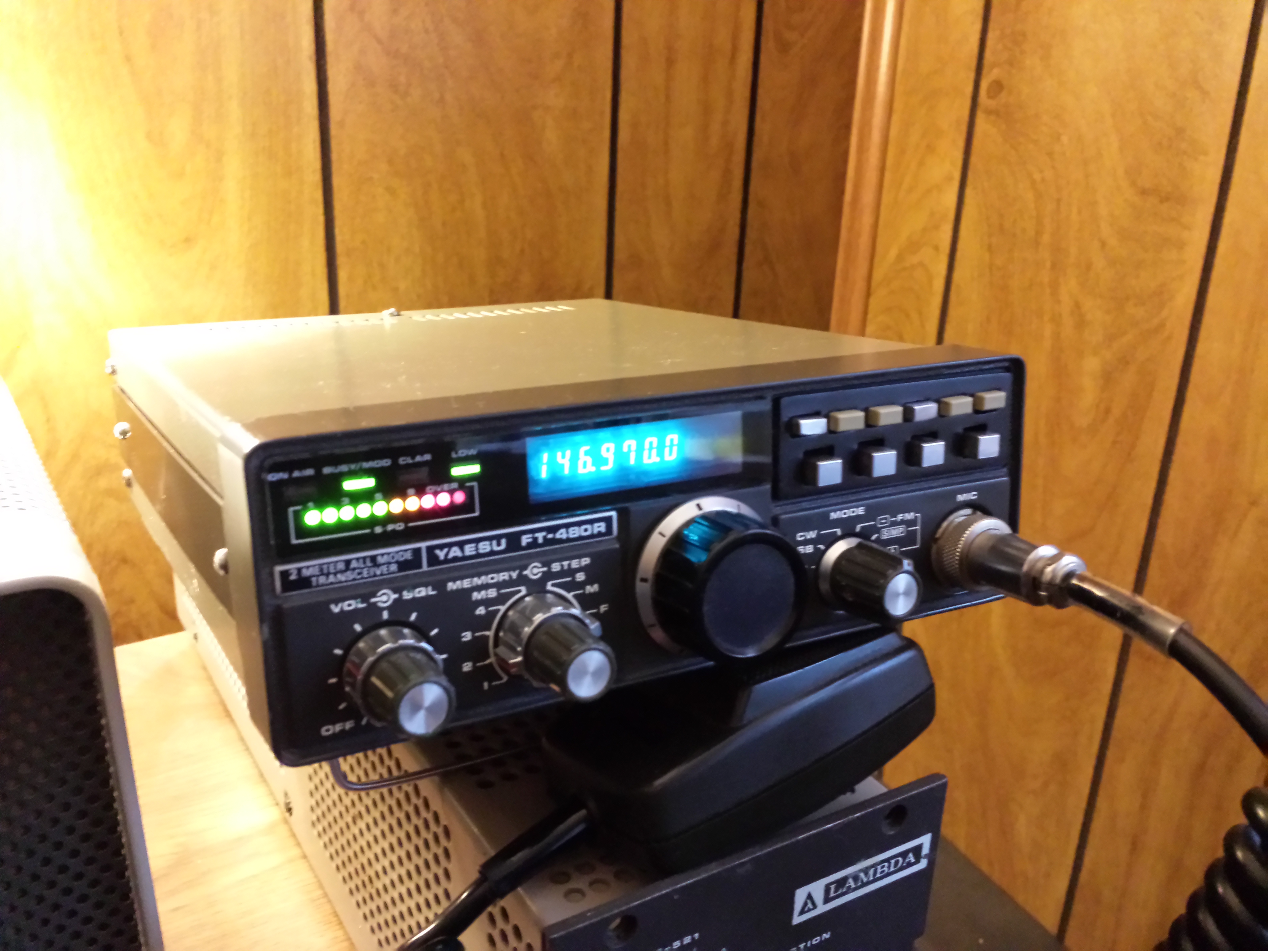
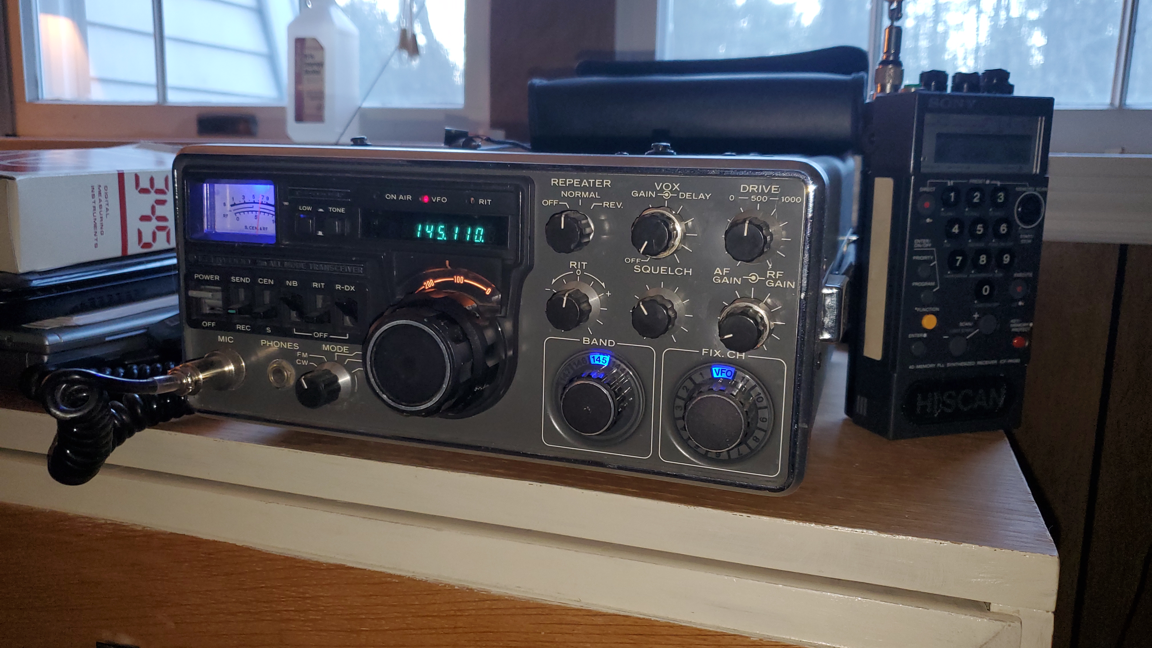
Yaesu FT-480R
Isolating failures in a radio with multiple problems can be challenging, a point proven by this FT-480R, which was acquired at a local hamfest as a parts radio. The CPU and display board functioned from the start, but every other subsystem had at least one fault. The main board had also seen some rewiring, not all of it accurate. Much of the case hardware was missing.
On the PLL board, the 10.24 MHz oscillator would not start. Replacing the crystal and removing the glue from the area surrounding the circuit did not remedy the problem. Consulting the application notes for the oscillator/divider IC showed that a small capacitor should appear between pin 1 and ground. Introducing this capacitor, which was left out by Yaesu, caused the oscillator to start reliably. Next, one of the three shift registers used to form a serial-to-parallel converter was faulty, making it impossible to set the master programmable divider. The shift register is a common part, still widely available. Finally, Yaesu used poor quality headers in this radio, and the connection bringing in the serial data from the controller board was noisy. Soldering a cheater line directly to the PLL board remedied this problem, allowing the PLL to function.
On the main board, the first transformer on the receiver side was open, preventing reception. Fortunately, the transformer can still be acquired from Yaesu America inexpensively. One of the diodes used for CW keying was open, and some of the associated wiring was incorrect and had to be altered to match the schematic. (This radio uses single-sided pc boards and is a nest of point-to-point wiring.) Significant realignment of the receiver and transmitter sections was also required.
At first, the final amplifier produced no output. This was corrected by adjusting the ALC verniers and those used to limit power under poor SWR conditions. At this point, however, the final amplifier became unstable, drawing full current in all modes and emitting off frequency. The problem was found to be due to the absence of the shield which is supposed to cover the entire amplifier assembly. Fitting an improvised shield finally let the amplifier run stably, producing rated power without distortion.
The all-mode radio now functions properly. The receiver is relatively sensitive and has a MDS of -135 dBm. It seems to be relatively free of spurs common to early synthesized radios. Adding CTCSS was straightforward. The radio is a creature of its times, however, replete with potentiometers, trimmers, and transformers requiring attention for proper operation. I suspect this radio may require frequent adjustment. It would not be a good choice for mobile use.
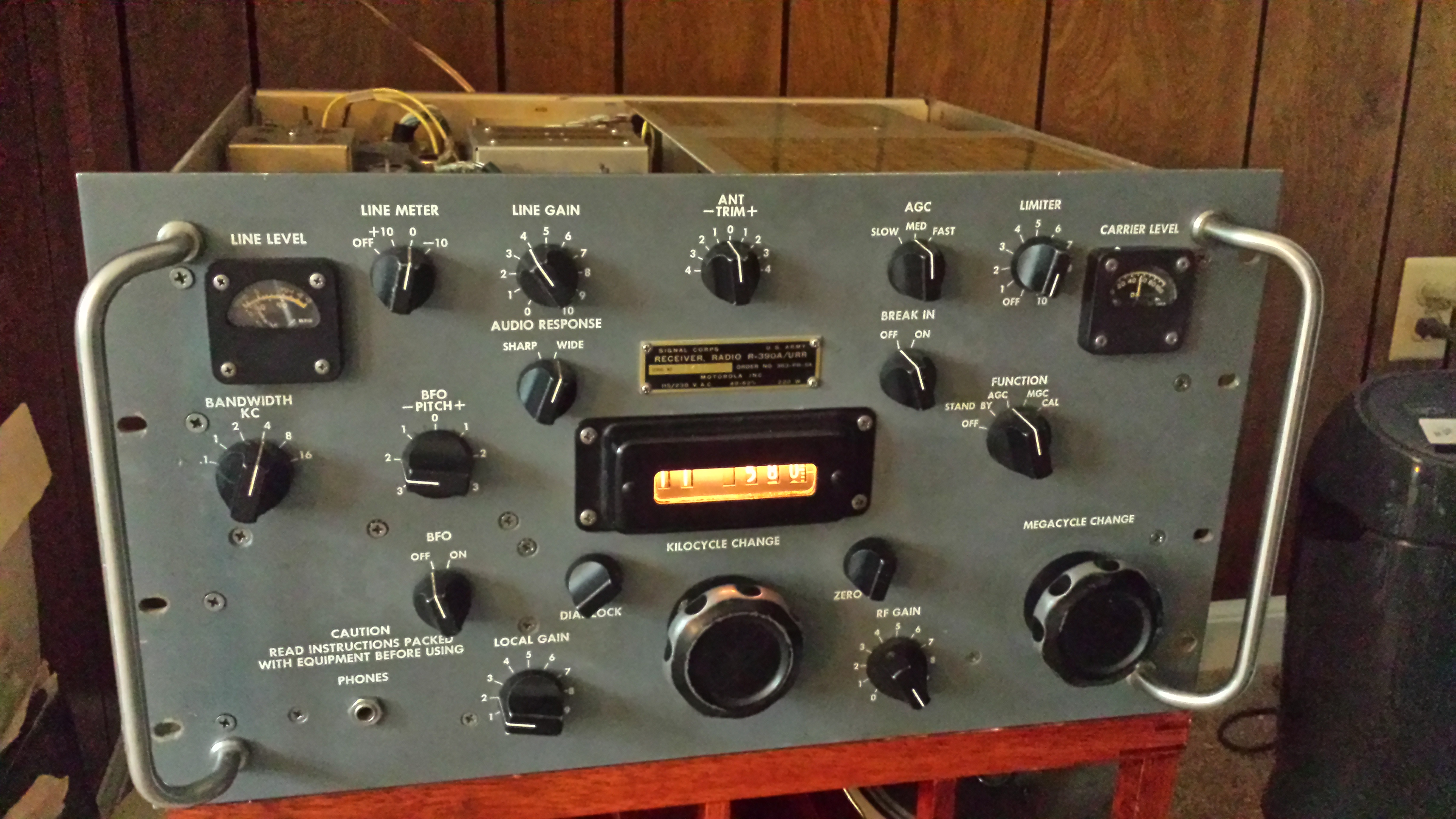
R390a (by Motorola)
There is little to add to the trove of information available about the R390a on the internet already. I was fortunate enough to acquire an unmodified unit that had previously served for years at a radar/communications station in the vicinity of Homer, Alaska. I fabricated new plug-in filter capacitors and replaced C-553 and C-609 before turning it on. The radio was badly misaligned, and the cams were not correctly synchronized. Several of the slugs were binding.
Having solved the aforementioned problems, I found that the 0.5-1 MHz and 2-4 MHz bands suffered from poor sensitivity and erratic behavior. The calibration points for the RF filter cans for these bands kept changing. Replacing one can apiece for each band with used cans from Fair Radio Sales remedied the problem. It seems that the mica capacitors inside these cans are beginning to fail.
The radio required no further service and performs admirably. The gear train is smooth and consistent.
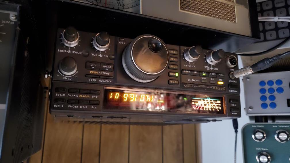
Yaesu FT-890 (with tuner)
This radio was acquired for nearly nothing at a local hamfest. The seller was reticent about discussing its condition other than to hint at stability problems with the reference oscillator. The seller wouldn't even say whether or not the radio powered up. The cosmetic condition of the radio was fair if worn, but the front panel was clean. Some improvised mounts were attached to either side of the radio in lieu of handles.
When powered, the radio was quiet although the digital functions seemed to work. In fact, the reference oscillator was working normally, but the 3rd local oscillator at 8.67 MHz in the RF unit was not. This turned out to be due to a misaligned ribbon cable between the RF unit and the local unit making the whole 3rd IF section inoperative. There was also a problem with the PLL that inhibited the full range of VFO tuning. That could be corrected by aligning the sub-loop DDS correctly (mainly by adjusting L1045).
Most likely, instability in the VFO prompted someone to open the unit, mis-adjust the PLL, and then mis-assemble the radio. Very little was wrong with it in the end. Over time, stability problems with the reference oscillator emerged, but this was corrected with the replacement of trimmer TC1002 on the local board. The AT-2 tuner also became unstable, but this could be repaired by retouching the relay solder joints on the main tuner board.
Overall, the radio remains a good performer with many options, and the documentaiton is excellent.
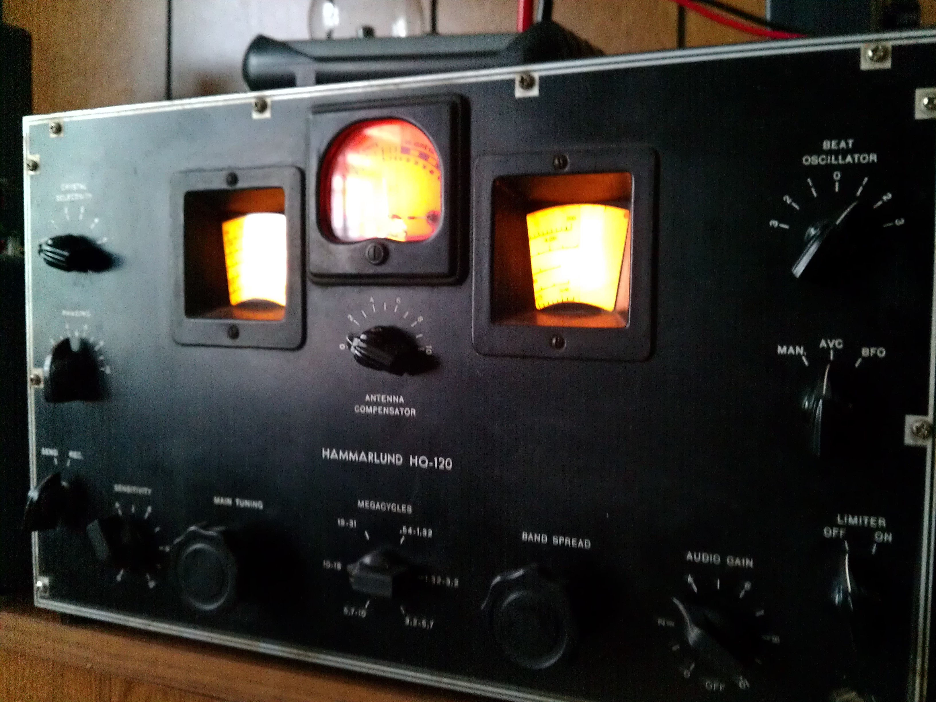
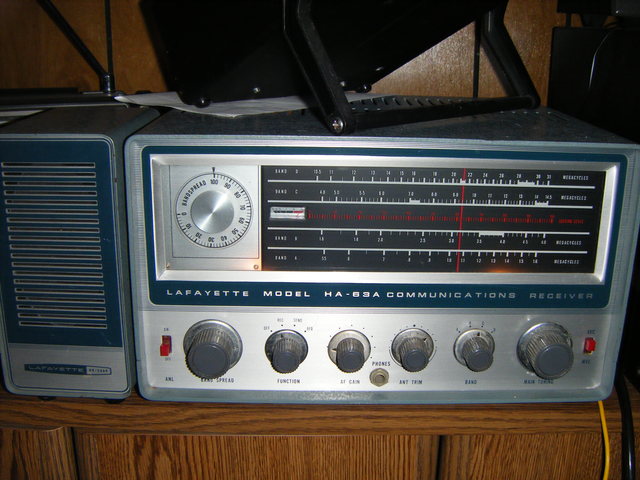
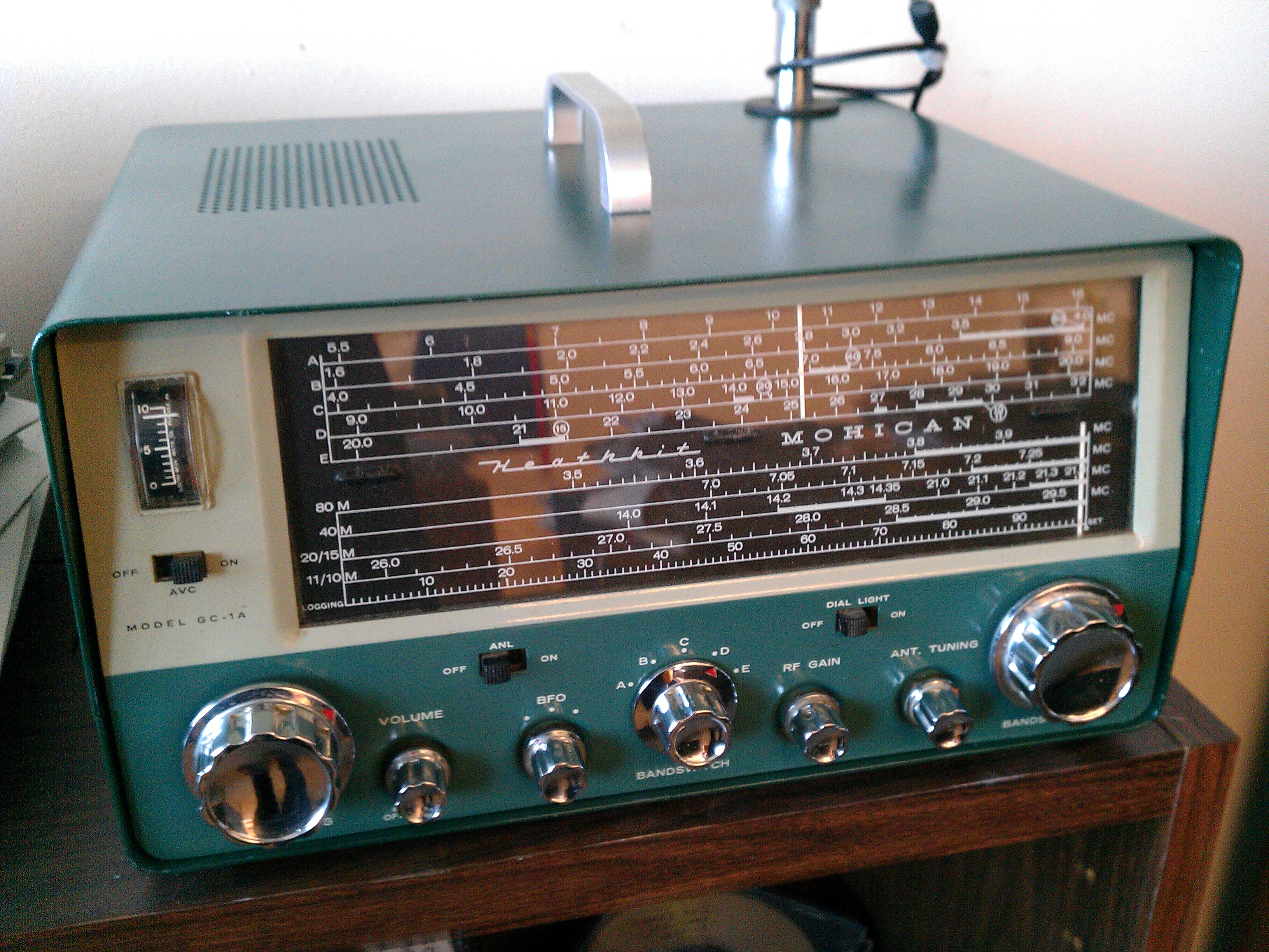
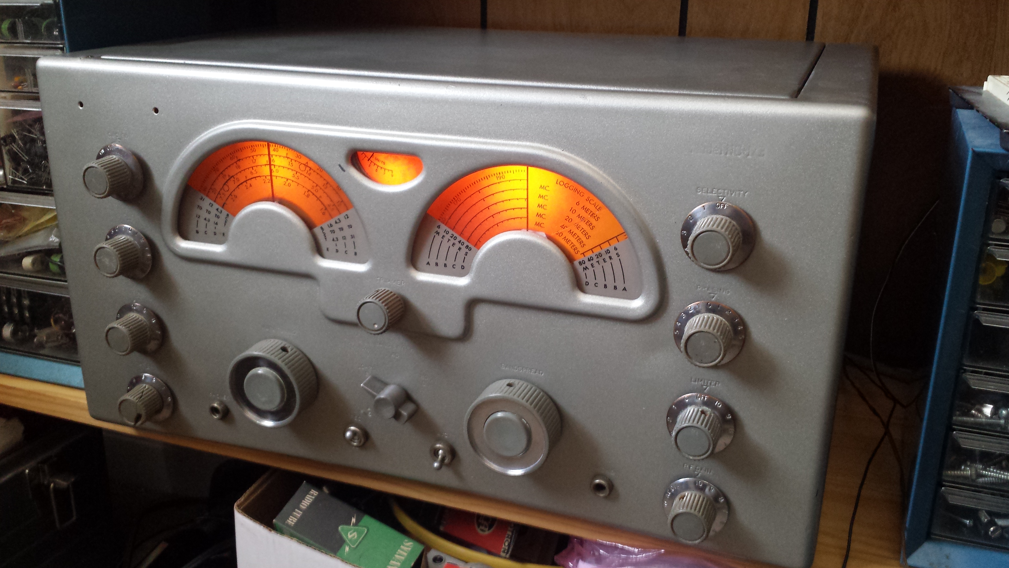
General coverage receivers
These include the Hammarlund HQ-120x, National 173, Lafayette HA-63a, and Heathkit Mohican, an early solid-state receiver. Of the four radios, the Hammarlund was easily the most interesting to work on. This one turned up in an unusual state. The detector, noise limiter, and audio preamplifier were wired along the lines of the HQ-129x for some reason, different tubes and all. While the radio worked this way, the wiring was poorly executed and unreliable. Reverting the radio back to the original circuitry restored reliability but did not change the performance appreciably. More than 20 paper capacitors were replaced with modern equivalents, although this too did little for performance. The radio is has reasonable sensitivity and selectivity but is prone to drifting.
Very similar to the Hammarlund is the National NC-173. This radio had spent the past few years exposed to the elements in a pole barn. It was found in a non-functioning condition and in pretty poor cosmetic shape. The filter capacitors in the power supply urgently needed replacement. Most of the plate and screen resistors were also well out of spec, and the detector had been rewired, intentionally or otherwise, in a way that prevented it from working properly. The HF oscillator and mixer tubes were also weak. After these problems were corrected, the radio worked pretty well. It is quite stable if not too sensitive on the upper bands. Most of the paper capacitors in this radio were replaced out of due diligence, but the performance did not improve markedly as a result.
In contrast, every electrolytic and paper capacitor in the Lafayette required replacement to make the radio work properly.
The Mohican is an unusual radio, constructed in the manner of its tube predecessors in terms of layout and weight. The radio uses only PNP transistors and employs a positive common chassis. The radio has a minimalist design and is not particularly sensitive or selective. The S-meter circuitry employs one less transistor than it should and deflects downward rather than upward. The S-meter itself is located too close to the speaker magnet which affects its displacement. Adjusting the S-meter for meaningful output is difficult. My radio had a defective electrolytic capacitor in the AGC circuit, causing it to distort badly with strong signals.
Summary
So, what components are most likely to fail? In solid-state radios, most of the faults described here involved semiconductors -- diodes, transistors, and integrated circuits. In vacuum-tube radios, many of the faults involved paper and electrolytic capacitors and carbon resistors. Common to both were faulty crystals, switches, and interconnects. Many faults also stemmed from questionable repairs or modifications. In a few cases, open coils and finicky trimmers were culprits. In no case were final amplifier tubes, transistors, or modules to blame.
Support links
Collins Collectors Association
Collins Compendium
PTO specs
PTO
adjustment guide
Fox Tango FT-200 site
LA8AK FT-200 page
210x mods page
Atlas VFO stabilizer
SB-102 information
SB-102 bulletins, etc.
SB-101, S-Line details
Drake TR7 information
Academic links
Ionospheric research at Cornell
National Astronomy and Ionosphere Center
Photos