DSP-620 transceiver
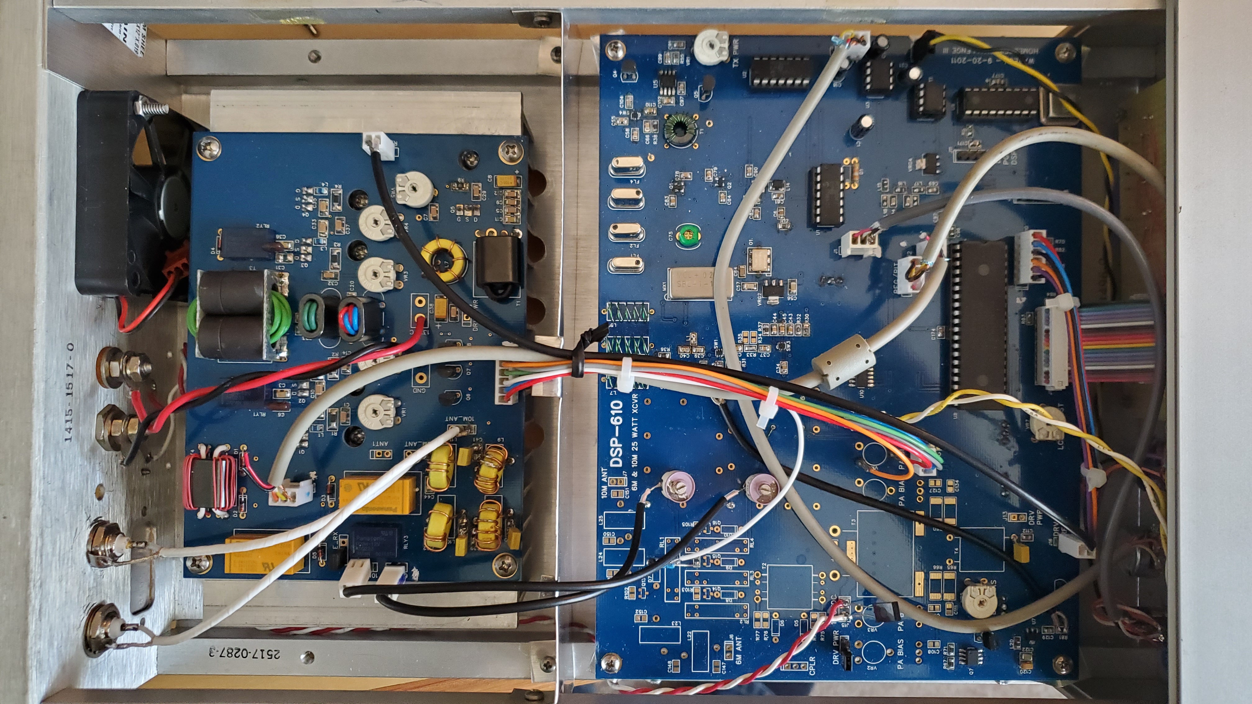
This page gives a description of a modified version of the DSP-610 transceiver developed by WA2EUJ and described here. The transceiver was the winner of the ARRL Homebrew Challenge III back in 2012. It combines traditional technologies (e.g. a legacy diode ring mixer) with some more advanced features (e.g. DSP, extensive use of smd components) and was designed to be constructed for approximately $200. (Parts are still available, but expect the cost today to be closer to $300.) The DSP-610 operates in the 6, 10, and 12 m bands and was supposed to deliver 25 W of power. Circuit boards are commercially available for the radio. These are high-quality boards, but the pads will lift if reworked excessively, so take care.
The radio described here operates in the 6, 15, 17, and 20 m bands. It makes use of the off-board power amplifier also developed by WA2EUJ and delievers 40 W on the HF bands and 30 W at VHF. More power could be obtained with more aggressive biasing. (For this project, the amplifier MOSFETs were biased to draw 150 mA quiescent current each.) Operation appears to be reliable and stable. As the software that drives the radio is quite compact and well documented, modifying the radio further would be straightforward.
A number of software and hardware modifications to the original project were required to make the DSP-620 function. On the software side, the most critical modification was to the routine that handles the inputs from the main rotary encoder. This code was originally part of the interrupt service routine for the PIC18F45K22 microcontroller, but rapid frequency tuning was unstable and caused the microcontroller to crash. Fortunately, the routine functions perfectly well outside the ISR, and simple polling is adequate to keep up with the rotary encoder. Adding debouncing capacitors to the encoders is also a good precaution.
The DSP code required modification as well. It is necessary to drive the gain of the IF amplifiers to zero during transmit to prevent internal feedback and the problems it creates.
Quite a few software modifications were required to change the frequency bands and number of bands. These were tedius but straightforward and are outlined in the aforementioned web link to the original project.
Modifying the frequency bands necessitated redesigns of the HF bandpass and lowpass filters. A helpful tool for passive filter design is available here. The new component values are shown in the table below. Also shown are a number of other component values that were changed to permit/improve overall performance. Some of the changes were needed to increase the system gain. A useful tool for designing multiple-feedback (MFB) active filters like the ones used in this radio is here.
| Component(s) | Original value | Modified value | Comment |
|---|---|---|---|
| FL1, FL2, FL3, Fl4 | ECS-10.7-15B | ECS-10.7-7.5B | narrower IF passband |
| D3, D4, D11, D12 | LED | small signal diode | adequate biasing |
| R12, R23 | 12 k | 1.2 k | adequate gain |
| L1A | 82 nH | 120 nH | improved stability |
| L2, L4 | 680 nH | 680 nH + 120 pF series | new HF bpf |
| L3 | 1.2 uH | 1.2 uH + 68 pF series | new HF bpf |
| C53, C54 | 150 pF | 470 pF | new HF bpf |
| L8, L9 | 150 nH | 150 nH | new HF bpf |
| C6, C31 (PA) | DNP | 68 pF | proper 6 m match |
| C43 (PA) | 220 pF | 180 pF | better 6 m match |
| L8, L9 (PA) | 9T | 8T | new HF lpf |
| C39, C41 (PA) | 220 pF | 120 pF | new HF lpf |
| C40 (PA) | 390 pF | 220 pF | new HF lpf |
A few more modifications to the original design were required. MCLR on the PIC19F45K22 must be pulled high through a resistor to function. This was omitted in the original circuit board. Some adjustment was also necessary for the circuit around Q19 to properly clock the PIC. While the DT signal for the PA board is available from R104 on the main board, the signals required for 6M and TX must be taken from the respective lines between the PIC and U10 on the main board.
Programming was done with MPLAB X IDE v 3.65 for linux using the c18 toolchain for the PIC and the xc16 toolchain for the DSP. The programmer used was the Olimex PIC-KIT3. This is a fine device with one caveat - the pin marked "1" is pin 6, not pin 1. Beware.
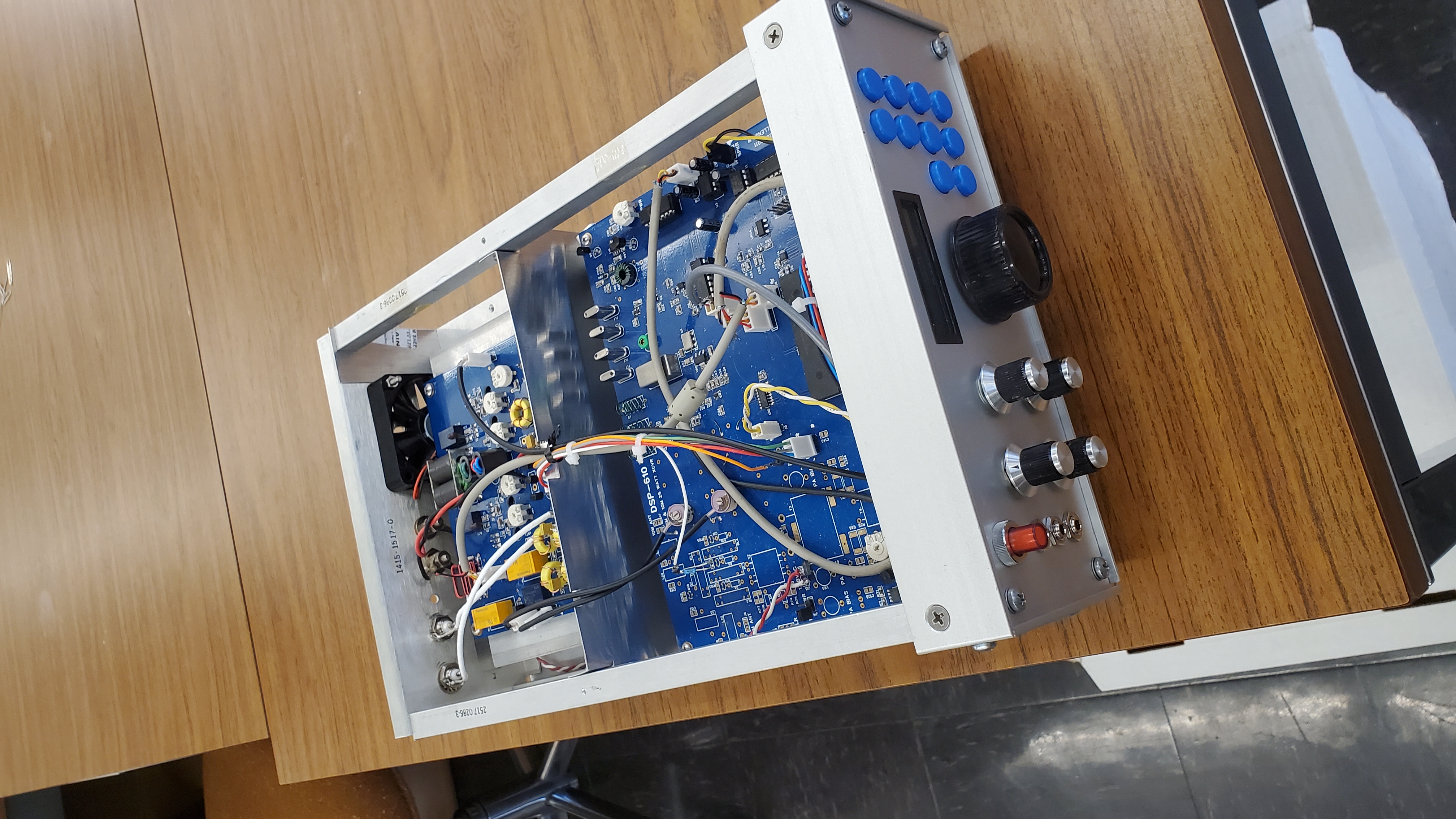
This transceiver was built in a cabinet recovered from a surplus medical device. The cabinet is made from longeron rods connecting end plates with an outer shell cover. It just accommodates the main and power amp boards. Note that adequate shielding between the PA board and the main board is essential. There is some room to spare for some additional components like an internal speaker and possibly a VOX system.
On the software side, it might be possible to add a notch filter and maybe voice compression. Split operation would be a nice feature too.
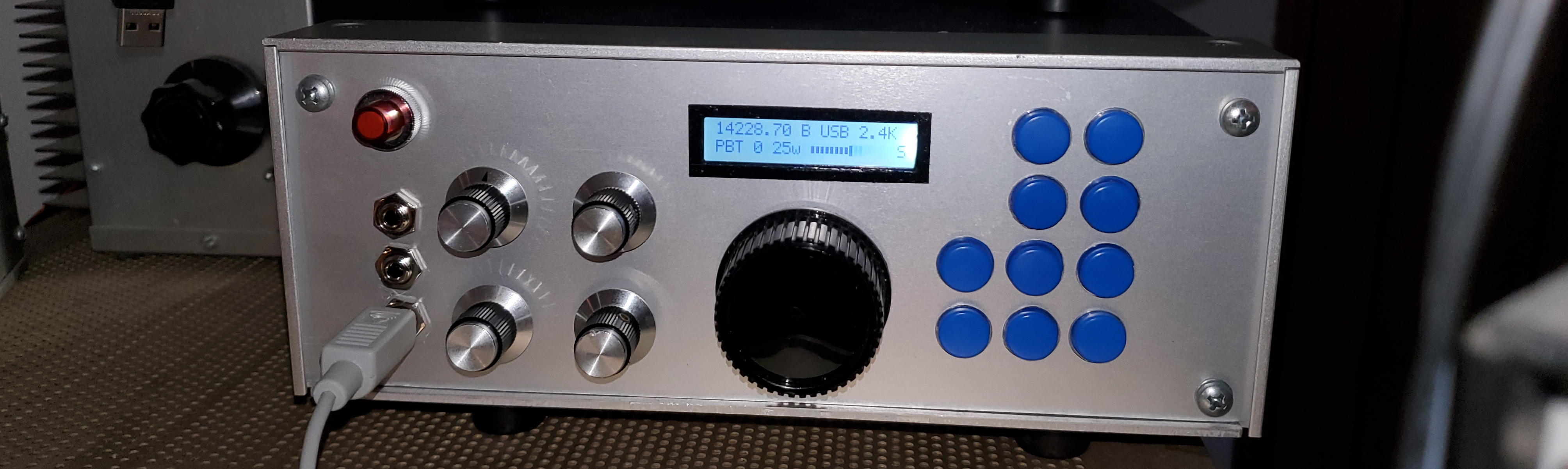
The radio still needs front-panel labels.
Gallery